Case Study: Optimising Substation Ventilation with CFD Simulation: A Cost-Effective Design Approach
- Shahram Derakhshan
- Feb 3
- 3 min read

Project: Substation Ventilation Optimal Design
Location: Parramatta, NSW
Introduction
Effective thermal management is crucial in substations to ensure the reliable operation of equipment, especially transformers. In this case study, we explore the use of Computational Fluid Dynamics (CFD) to assess and optimise the natural ventilation system for a substation room. The study evaluates the performance of the two-stage louvre ventilation system designed to manage heat dissipation from 1500 kVA, 11 kV dry-type transformers, ensuring compliance with industry standards and optimal operating conditions.
Project Overview
The substation room is designed with a natural ventilation system featuring a two-stage louvre setup. Fresh air enters through the louvres, circulates to absorb heat generated by the transformers, and exits through the same system. The CFD simulation was conducted to verify that the ventilation system effectively keeps the room temperature within the permissible limits of 5°C above ambient, as specified in MCI 0006: Underground Distribution Construction Standards Manual.
Objectives of CFD Simulation
Evaluate the airflow characteristics through the louvre system to ensure optimal heat dissipation.
Confirm that room temperatures stay within the specified limits, even under extreme ambient conditions.
Assess the overall performance and effectiveness of the natural ventilation system.
Substation Room Details
The room houses two 1500 kVA, 11 kV dry-type transformers, generating a total heat load of 40 kW. Ventilation is achieved entirely through the two-stage louvre system, designed to meet MCI 0006 standards and maintain a room temperature not exceeding 5°C above ambient.
Key Assumptions
Heat Dissipation: Total transformer load loss assumed at 40 kW, as per MCI 0006.
Temperature Criteria: The room temperature at 1.8 m above the floor should not exceed 5°C above ambient.
Louvre System: Two-stage louvre system with 50% free area ratio, including bird wire mesh.
Ventilation Method: Natural ventilation through temperature-driven stack effect.
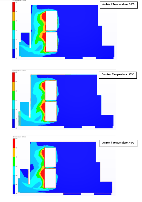
Environmental Conditions: Ambient temperatures of 30°C, 35°C, and 40°C were considered, with a mean wind speed of 9.8 km/h.
Ventilation Calculations
The required airflow for heat dissipation was calculated based on the total heat load of 40 kW. The analysis showed that the existing louvre area was adequate to maintain the room temperature within the 5°C threshold.
Required Airflow: 6.64 m³/s
Effective Louvre Area: 8 m² (split between intake and exhaust)
Average Air Velocity: 1.66 m/s
Adding extra louvres reduced the average air velocity to 1.17 m/s, ensuring sufficient airflow for optimal cooling.
CFD Analysis Methodology
Geometry & Mesh Development:
A detailed 3D CAD model was created based on architectural and mechanical drawings.
A fine mesh with one million elements was utilised for accurate resolution of local gradients.

Substation room 3D CAD geometry Solver Setup & Boundary Conditions:
Simulations were performed using Autodesk CFD 2024.
The pressure-based solver employed the k-ε turbulence model, suitable for moderate Reynolds number flows.
Inlet conditions: Outdoor ambient temperature and air velocity.
Outlet conditions: Atmospheric pressure applied at exhaust louvres.
Heat sources: Transformer load losses defined as volumetric heat generation.
Results
The CFD simulation confirmed that the two-stage louvre system effectively managed the room’s thermal conditions. Temperature distribution remained within the 5°C above ambient limit, even at maximum ambient temperature conditions. The airflow patterns and temperature contours verified that the system performed as intended, ensuring efficient operation of the transformers.

Compliance with Standards
The ventilation system complies with the MCI 0006 standards, which stipulate a maximum temperature rise of 5°C above ambient. The CFD results confirm that the system meets these criteria under all assessed conditions, ensuring reliable equipment operation.
Conclusion
This case study demonstrates how CFD simulation can optimise substation ventilation systems, ensuring compliance with industry standards and effective thermal management. The natural ventilation system, designed with a two-stage louvre configuration, successfully maintains the required temperature differential, confirming the system’s effectiveness in dissipating heat and supporting transformer reliability. Through CFD analysis, engineers can validate ventilation designs and enhance the efficiency and longevity of critical infrastructure.
Comments